In Wireless LANs CSMA/CA is core concept in comunicating wirelessly. In any shared medium accessing the medium without collision is important part. Its like not talking all at a time, so that remaining people should understood the other's talk.
In Ethernet it is achieved through CSMA/CD as it is using full duplex communication. But in wireless it is using Halfduplex communication. The half-duplex constraint applies to devices that share a relative physical area and RF frequency.Several mechanisms are used as a part of 802.11 channel access to minimize the likelihood of frame collisions by multiple STAs attempting to access the transmission medium simultaneously.
Collisions often occur, but the processes used by the 802.11 protocol are in place to minimize the likelihood of collisions and define the appropriate response in the event that a collision is inferred.
Two most common coordination access methods used in WLANs
1.Distributed Coordination Function (DCF)
2.Enhanced Distributed Coordination Access (EDCA is part of HCF).
1. Distributed Coordination Function (DCF)
- Using the foundational DCF coordination function logic is active in every station (STA) in a basic service set (BSS) whenever the network is in operation.i.e. each station within a DCF follows the same channel access rules.
- This method is contention-based, which means that each device “competes” with one another to gain access to the wireless medium.
- After a transmission opportunity is obtained and observed, the contention process begins again.
- As the original 802.11 network access method, DCF is the most simple channel access method but it lacks support for quality of service (QoS).
- In order to maintain support for non-QoS devices in QoS-enabled networks, support for DCF is required for all 802.11 networks.

2. Hybrid Coordination Function (HCF)
- As an optional access method that may be used in addition to DCF, HCF was introduced to support QoS.
- HCF assimilated elements of both DCF and PCF mechanisms, creating a contention-based HCF method, called EDCA, and a contention-free HCF method, called HCCA.
- EDCA inaugurated a means of prioritizing contention-based wireless medium (WM) access by classifying 802.11 traffic types by User Priorities (UP) and Access Categories (AC).
- There are a total of 8 UPs, which map to 4 ACs.
- EDCA is used by stations that support QoS in a QoS BSS to provide prioritized WM access, but HCF is not used in non-QoS BSSs.

3.Point Coordination Function (PCF)
- As an optional PCF is a contention-free access method.
- PCF provides polling intervals to allow uncontended transmission opportunities for participating client devices.
- In this approach, the AP of a BSS acts as a point coordinator (PC), initiating contention-free periods in which prioritized medium access is granted to clients, one at a time.
- PCF has gone unused in 802.11 WLANs.
Summary
• DCF is the fundamental, required contention-based access service for all networks
• PCF is an optional contention-free service, used for non-QoS STAs
• HCF Contention Access (EDCA) is required for prioritized contention-based QoS services
• HCF Controlled Access (HCCA) is required for parameterized contention-free QoS services
802.11 Channel Access Mechanisms
Both contention-based access methods described previously (i.e. DCF and EDCA) employ similar mechanisms to moderate channel access and to minimize collisions.
Below is Outline for Channel Access:
1. STAs use a physical carrier sense (Clear Channel Assessment—CCA) to determine if the WM is busy.
2. STAs use virtual carrier sense (Network Allocation Vector—NAV) to detect if the WM is busy. When the virtual timer (NAV) reaches zero, STAs may proceed.
3. If conditions 1 and 2 are met, STAs wait the necessary IFS interval, as prescribed by the protocol.
4. If conditions 1 and 2 are met through the duration of condition 3, STAs generate a random backoff number in accordance with the range of allowed values.
5. STAs begin decrementing the backoff timer by one for every slot time duration that the WM is idle.
6. After decrementing the backoff value to zero, with an idle medium, a STA may transmit the allotted frame exchange, in accordance with the parameters of the obtained transmission opportunity.
7. If another STA transmits before Step 6 is completed, STAs observe steps 1, 2, 3, and 5 until the backoff timer is equal to zero.
8. After a successful transmission, repeat as needed.

Carrier Sense
- 802.11 WLANs uses Carrier Sense Multiple Access with Collision Avoidance (CSMA/CA).
- For STAs to cooperate effectively on a half-duplex channel, each STA must be able to determine when the medium is clear, and when another device is actively transmitting.
- The physical carrier sense uses the physical radio interface to sample the wireless medium to detect transmissions. Virtual carrier sense refers to the use of Duration values in the MAC header of a frame and NAV timers to virtually determine if another STA is transmitting.
- These two mechanisms determine the status of the medium, whether idle or busy.
Physical Carrier Sense
- The physical carrier sense mechanism defined by IEEE is known as clear channel assessment (CCA).
- CCA is the physical measurement taken by a radio interface to determine if the wireless medium is currently in use. The physical layer, which can be divided into two sublayers—the physical medium dependent (PMD, lower sublayer) and the physical layer convergence procedure (PLCP, upper sublayer)—performs this task and communicates this information to the MAC.
- According to the CCA mode in use, the PMD issues service primitives to the PLCP sublayer indicating whether the wireless medium is in use.
- The PLCP sublayer then communicates with the MAC layer to indicate a busy or idle medium, which prevents the MAC from attempting to forward a frame for transmission.
- Each PHY within the 802.11-2007 standard dictates the specific operations and signal thresholds used to carry out the CCA mechanism.
- CCA can be divided into two separate processes: Energy detection (ED) and carrier sense (CS).
- ED functionality is based upon raw RF energy. When an energy level detected in the channel crosses a certain threshold for a certain period of time, the “busy medium” indication will be triggered.
- On the other hand, CS—more precisely, “preamble detection”—monitors and detects 802.11 preambles, which are used to trigger the CCA mechanism and indicate a busy medium.
Virtual Carrier Sense

- Virtual carrier sense mechanism is defined in addition to the physical carrier sense.
- Virtual carrier sense uses information found in 802.11 frames to predict the status of the wireless medium.
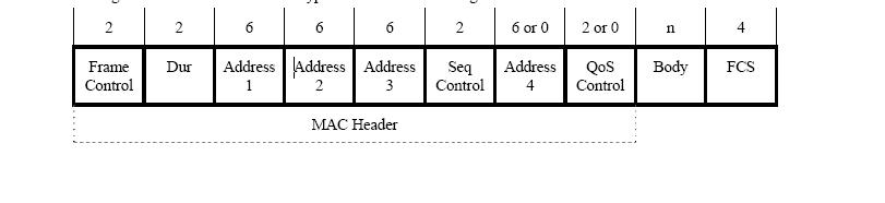
- This is performed by means of the network allocation vector (NAV), which is a timer that is set using the duration values in the MAC header of a frame.
- Each frame contains a duration value, indicating the time required for a station to complete the conversation.
- All STAs use these duration values to set their NAV, and then they count down the NAV timer, waiting for the medium to become available.
See the Duration Filed in MAC header in below Pic (second filed)
- All STAs attempt to process all frames—and a minimum of the first in a frame exchange—on their channel.
- The first frame in a frame exchange is significant because it can, and sometimes must, be used to determine how long a given transmission opportunity will occupy the wireless medium.
See below wireless capture for Duration value

- The MAC header of each frame contains a Duration field, which indicates the amount of time necessary to complete the entire frame exchange, or the entire TXOP duration.
- In DCF, a transmission opportunity only allows for the transmission of one frame, thus the Duration value represents the required IFS interval and the acknowledgement frame (ACK), if one is required.
- The exception to this rule is for networks in which RTS/CTS or CTS-to-self protection is enabled. In this case, the transmission opportunity allows for the use of these frames.
- In HCF, several frames may be transmitted within a transmission opportunity. Thus, the Duration value refers to the TXOP duration.
- In either case, non-transmitting STAs must remain idle while the medium is reserved.
- When STAs read the Duration value in a frame, they set their NAV timer accordingly and count down this duration.
- The duration value in the MAC header indicates the time required to complete the transmission opportunity after the current—the frame in which the Duration value resides—frame if completed.
- If a STA is counting down its NAV and it receives another frame with a longer duration (would increase its NAV), the STA increases its NAV accordingly.
- Conversely, when a STA receives a frame with a shorter duration value (would decrease its NAV), the STA ignores this value and continues to observe the longer NAV duration.
See below RTS / CTS exchange

- In networks where mixed PHY technologies are supported, protection mechanisms are enabled to satisfy the equirements of frame processing and adherence to the common channel access protocol.
- Frames used as a protection mechanism (often an RTS/CTS exchange or CTS-to-Self) are transmitted at a common rate understood by all PHYs in the network.
- Legacy PHY STAs read the Duration value in the protection frame(s), set their NAV timer.
Interframe Spacing (IFS)
- After each frame transmission, 802.11 protocols require an idle period on the medium, called an interframe space (IFS).
- The length of the IFS is dependent upon a number of factors, such as the previous frame type, the following frame type, the coordination function in use, the access category of the following frame (in a QoS BSS), as well as the PHY type.
- The purpose of an IFS is both to provide a buffer between frames to avoid interference as well as to add control and to prioritize frame transmissions.
- Each IFS “is the time from the end of the last symbol of the previous frame to the beginning of the first symbol of the preamble of the subsequent frame as seen at the air interface

In other words, the IFS interval is observed beginning with the completion of the previous frame. The length of each IFS interval, excluding AIFS, is fixed for each PHY
Short Interframe Space (SIFS)
- SIFS are used within all of the different coordination functions.
- For 802.11-2007, SIFS is the shortest of the IFSs and is used prior to ACK and CTS frames as well as the second or subsequent MPDUs of a fragment burst.
- However, with 802.11n, a shorter IFS (RIFS) was introduced.
- The IEEE explains the use of SIFS accordingly:
“SIFS shall be used when STAs have seized the medium and need to keep it for the duration of the frame exchange sequence to be performed. Using the smallest gap between transmissions within the frame exchange sequence prevents other STAs, which are required to wait for the medium to be idle for a longer gap, from attempting to use the medium, thus giving priority to completion of the frame exchange sequence in progress.”
- SIFS is used as a priority interframe space once a frame exchange sequence has begun.
- This is true when multiple frames are transmitted within a TXOP (as with frame bursting) and it is also true when a single frame is transmitted (as with typical data-ack exchanges).
PCF Interframe Space (PIFS)
- PIFS are used by STAs during the contention-free period (CFP) in PCF mode.
- Because PCF has not been implemented in 802.11 devices, you will not see PIFS used for this purpose.
- However, PIFS may be used as a priority access mechanism for Channel Switch Announcement frames, as used to meet DFS requirements.
- In order to gain priority over other STAs during contention, the AP can transmit a Channel Switch Announcement frame after observing a PIFS.
DCF Interframe Space (DIFS)
- When a STA desires to transmit a data frame (MPDU) or management frame (MMPDU) for the first time within a DCF network, the duration of a DIFS must be observed after the previous frame’s completion.
- The duration of a DIFS is longer than both the SIFS and PIFS.
Arbitration Interframe Space (AIFS)
- The AIFS shall be used by QoS STAs to transmit all data frames (MPDUs), all management frames (MMPDUs), and the following control frames: PS-Poll, RTS, CTS (when not transmitted as a response to the RTS), BlockAckReq, and BlockAck (when not transmitted as a response to the BlockAckReq) With EDCA.
- The basic contention logic is the same as with non-QoS networks, but in order to facilitate QoS, there are some notable differences.
- While DCF can designate a single DIFS value for each PHY, EDCA establishes unique AIFS durations for access categories (AC).
- For this reason, an AIFS is typically notated as an AIFS[AC].
- QoS STA’s TXOPs are obtained for a specific access category, so delineation between ACs must be made.
- For improved control of QoS mechanisms, AIFS values are user-configurable.
- By default, QoS APs announce an EDCA parameter set in the Beacon frame that notifies stations in the BSS about QoS values.
- By changing these values in the AP configuration, the AP will broadcast a different set of parameters to the BSS.
Extended Interframe Space (EIFS)
- The EIFS value is used by STAs that have received a frame that contained errors.
- By using this longer IFS, the transmitting station will have enough time to recognize that the frame was not received properly before the receiving station commences transmission.
- If, during the EIFS duration, the STA receives a frame correctly , it will resume using DIFS or AIFS, as appropriate.
Reduced Interframe Space (RIFS)
- RIFS were introduced with 802.11n to improve efficiency for transmissions to the same receiver in which a SIFS-separated response is not required, such as a transmission burst.
See below Pic for IFS comparison

- The graphic demonstrates the relationship between the different IFS intervals.
- You will notice that the initial frame (“Busy Medium”) transmission is preceded by a DIFS or AIFS.
- The graphic shows the relative relationship of the IFS lengths.
- SIFS are the shortest IFS (excluding 802.11n’s RIFS) and PIFS are second shortest, while DIFS and AIFS take up the caboose.
- SIFS, PIFS, and RIFS are used to provide priority access for a given type of frame, which eliminates the need for added contention
Calculating an Interframe Space
The 802.11-2007 specification provides the information necessary for us to calculate the durations for each IFS.
As noted previously, SIFS, PIFS, and DIFS are fixed values for each PHY, while AIFS will vary in accordance with the AC in use.
EIFS are fixed per PHY in DCF networks, but vary when used with EDCA.
The formulas and components used for SIFS, PIFS, DIFS, EIFS, and AIFS calculations are as follows:
aSIFSTime = aRxRFDelay + aRxPLCPDelay + aMACProcessingDelay + aRxTxTurnaroundTime
aSlotTime = aCCATime + aRxTxTurnaroundTime + aAirPropagationTime+ aMACProcessingDelay.
The “aSIFSTime” is the same as a SIFS, measured in microseconds (µs). Similarly, the “aSlotTime” is the same as a slot time. Both of these values are provided for each PHY in the 802.11 specification.
PIFS = aSIFSTime + aSlotTime
DIFS = aSIFSTime + 2 × aSlotTime
Given that the SIFS and slot time values are provided for us in the standard, these calculations are pretty simple.
See below IFS calculations

EIFS (DCF) = aSIFSTime + DIFS + ACKTxTime
In this formula, the “ACKTxTime” is the amount of time it takes to transmit an ACK frame at the lowest mandatory rate in the BSS.
EIFS (EDCA) = aSIFSTime + AIFS[AC] + ACKTxTime
The EIFS (EDCA) formula mirrors the same for DCF, but replaces the DIFS with the appropriate AIFS[AC].
An AIFSN is a number (AIFS Number) value that is user-configurable and determines the brevity (or length) of an AIFS interval. AIFSN values are set for each access category, giving the AIFS[AC] a shorter or longer duration, in accordance with the desired priority.
This is demonstrated by the AIFS[AC] formula:
AIFS[AC] = AIFSN[AC] × aSlotTime + aSIFSTime
Your technical material and presentation is Outstanding
ReplyDeletesriram
Thanks for such a wonderful material
ReplyDeleteLife Saving <3
ReplyDeleteWonderful
ReplyDeleteExplained it well
Excellent, thanks for knowledge
ReplyDeleteGreat Article , Thumbs Up
ReplyDeletenice
ReplyDeleteNice Post Keep Posting like this on regular basis.Hack Wifi Password
ReplyDeleteHousefull 4 Full Movie Download
ReplyDeleteNice Post. I like your blog. Thanks for Sharing.
ReplyDeleteWiFi Speed Test
You will find a lot of approaches after visiting your post.Thanks for sharing the such information with us to read this...
ReplyDeletegirls dresses
WiFi Speed Test
ReplyDeletemmorpg
ReplyDeleteinstagram takipçi satın al
Tiktok jeton hilesi
TİKTOK JETON HİLESİ
Sac ekimi antalya
INSTAGRAM TAKİPCİ
İNSTAGRAM TAKİPÇİ SATIN AL
Mt2 Pvp
TAKİPCİ SATIN AL
Perde Modelleri
ReplyDeletemobil onay
mobil ödeme bozdurma
nft nasıl alınır
Ankara evden eve nakliyat
trafik sigortasi
Dedektor
Website.kurma
aşk kitapları
amasya
ReplyDeleteantakya
edirne
elazığ
kayseri
MTLRCW
salt likit
ReplyDeletesalt likit
dr mood likit
big boss likit
dl likit
dark likit
VDOHJW
حشرات
ReplyDeleteمكافحة الحشرات
شركة صيانة كاميرات مراقبة
ReplyDeleteصيانة كاميرات مراقبة
شركة فك وتركيب مطابخ
ReplyDeleteفك وتركيب مطابخ
شركة تسليك مجاري في الشارقة thARRKZJNH
ReplyDeleteشركة تنظيف مساجد بالجبيل
ReplyDeleteDiDuYkbJeLQbNM
شركة مكافحة حشرات بالاحساء
ReplyDeletepmRD2DuRwKn3oi4